When designing injection molded plastic parts, here are some simple rules to follow that will help to ensure higher-quality parts that are easier to manufacture:
Maintain Uniform Wall Thickness
Maintaining uniform wall thickness is the single best design element you can incorporate in injection molded plastic parts. Uniform wall thickness promotes uniform filling patterns, uniform molded-in stress distributions, uniform shrinkage and ultimately, molded parts that are much less likely to warp out of shape compared to parts that have significantly varying wall thickness. This image shows the Nominal Wall Thickness Adviser plot from SOLIDWORKS Plastics 2015, which indicates areas that deviate significantly from the nominal wall thickness. You can then use this information to modify wall thicknesses and arrive at a final design with more uniform wall thickness. Hint: While most injection molded parts are thin-walled in nature, look for thick sections in your designs that can be cored-out to maintain the overall uniformity of the nominal wall thickness.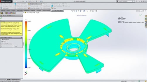
Avoid Abrupt Transitions From Thin to Thick
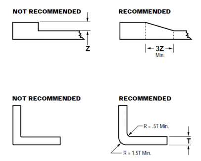
 It’s inevitable that your parts will require some variations in wall thickness due to the incorporation of structural features such as ribs, bosses and gussets. However, the transition from thin to thick should be as gradual as possible in order to avoid mold-filling phenomena such as flow hesitation or racetracking. Given a choice, molten plastic flowing inside of an injection mold cavity will always take the path of least resistance, typically towards the thicker wall sections. Flow hesitation occurs when the melted plastic flows into a thicker section while the flow in the thinner section stalls and sometimes freezes off completely, causing major problems. Racetracking occurs when the molten plastic “races” around the edges of a part due to thicker wall sections around the perimeter of the part compared to the interior wall sections. Maintaining gradual transitions from thin to thick– as seen in the diagram–can help reduce these phenomena or eliminate them altogether, resulting in higher-quality molded parts with fewer manufacturing defects.
Folow Rib Design Guidelines
Ribs are commonly used in plastic parts to provide structural integrity, prevent part warpage and aid in the integration ofinternal components. However, if ribs are not designed properly relative to the surfaces they’re attached to, problems such as sink marks, warpage and part failure can occur. The following rib design guidelines work well for most plastics materials: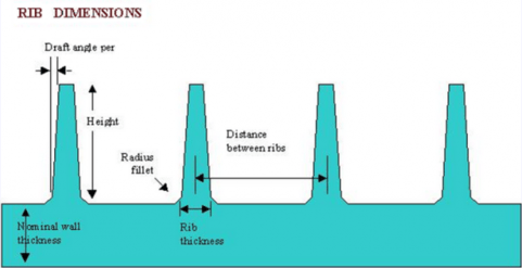
- Rib thickness at the base should be between 50-70% of the nominal wall thickness.
- Rib height should be 2.5 – 3X the nominal wall thickness.
- Ribs should have 0.5 – 1.5 degrees of draft (for ejection).
- Rib base radii should be 0.25 – 0.4X the nominal wall thickness.
- The distance between two ribs should be 2 – 3X the nominal wall thickness.
Avoid Sharp Corners
Sharp corners in plastics parts act as stress concentrators that can lead to crazing, cracking, increased susceptibility to chemical attack and ultimately, part failure – so it’s a really good idea to avoid them at all costs. The good news, it’s usually pretty easy to add fillets or chamfers to avoid sharp corners altogether as can be seen in this diagram.
Now that you we’ve covered some of the most important rules to follow when designing injection molded plastic parts, you should watch our 22-minute webinar on Better Plastics Part Design. And until next time…clear your mind, focus and GET THAT PROJECT DONE!
By Peter Rucinski
SUBMIT YOUR COMMENT