
While industrial-grade print quality and engineering-grade materials are now available on fast, affordable consumer 3D printers, I find that many SOLIDWORKS users remain intimidated by Design for Additive Manufacturing (DFAM) principles. As a result, they fail to get the most out of their hardware.
In this article, we’ll look at some of my favorite design tips for 3D printing — presented through a couple of practical SOLIDWORKS case studies that will help you get the most out of your 3D printer.
Note: This article focuses primarily on tips for Fused Deposition Modeling (FDM) process for printers common in the consumer and prosumer markets such as Bambu Labs, Prusa, Creality, Markforged, etc.
Case Study: Snowblower Chute Spacer
The first example I’ll cover is a spacer I designed and printed as part of an effort to “restomod” a 1971 Ariens Sno-Thro snowblower. The original Tecumseh engine finally let go after 50+ years and it was time to replace it with the finest motor Harbor Freight had to offer. The new motor bolted on without any need for custom fabrication, but the linkage that controlled the rotation of the snow chute wouldn’t clear the new, larger cylinder heads.
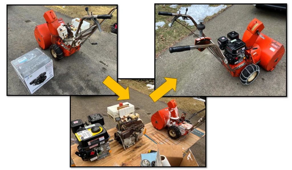
Eventually, I determined that by angling the linkage down and away from its original location would clear the cylinder head, but determining the exact dimensions required for this compound angle seemed difficult. Instead of trying to measure it precisely, I batch-printed a set of alternate configurations to swap out and find the ideal fit.
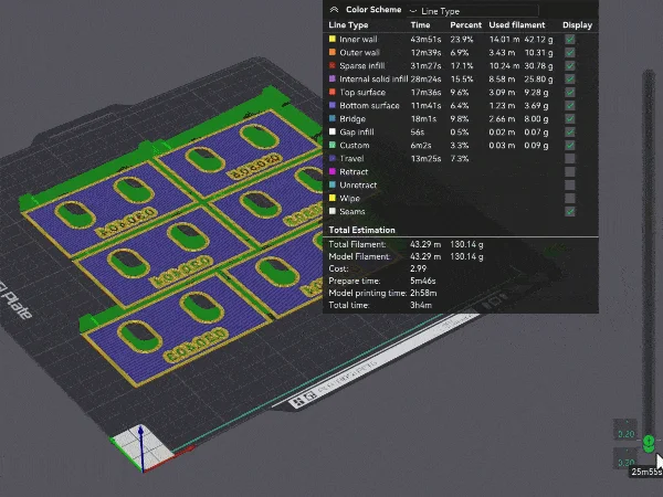
Above, you can see the batch of finished spacers prepared for printing with an estimated total cost of under $3 of PLA (modern slicers provide cost estimation at slice time for various filaments), making this brute-force approach at prototyping very cost-effective.
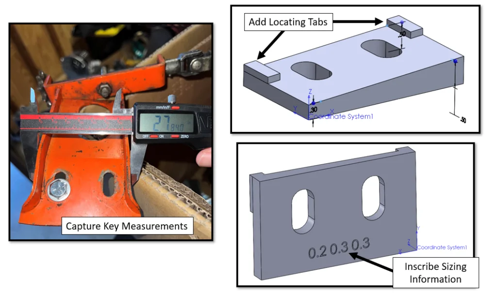
To model the spacer, I captured some of the key dimensions using a pair of calipers and decided to add some locating tabs to make placing the spacer and slipping the bolts through easier.
On the rear of the model, I inscribed the configuration name and sizing information (cut one layer deep) in case I ever need to reprint it. This is a habit I’ve gotten into for almost any print since it takes barely any additional print time and results in a legible part identifier that won’t easily wear off.
I utilized a 3D sketch with three sketch points to control the compound angle of the upper face, which was easy to vary across multiple configurations. I created a Coordinate System to export my STL files as Z-up and avoid the need for rotation or additional positioning in the slicing software, and I exported each STL file so they could be printed on a single build plate.
To read the full article, click here.
Click here to learn more, get a quote, or contact an expert at The SolidExperts.
Want to learn more and take a deep dive into SOLIDWORKS? Check out our upcoming training classes to enhance your SOLIDWORKS skills. All classes are offered in person and virtually.



SUBMIT YOUR COMMENT