In the October blog we looked at the default gauge tables included in the SOLIDWORKS installation.
In order to understand how gauge or bend tables work we must understand the sheet metal parameters controlled by these tables.
This month we will be concentrating on understanding those parameters.
The sheet metal parameters to understand when dealing with bend tables are:
- Bend radius
- Bend Angle
- Flatten length (bend region)
- Bend Allowance
- Bend Deduction
- K-factor
The bend radius is the inner arc radius produced when bending a sheet metal body (Fig. 1)

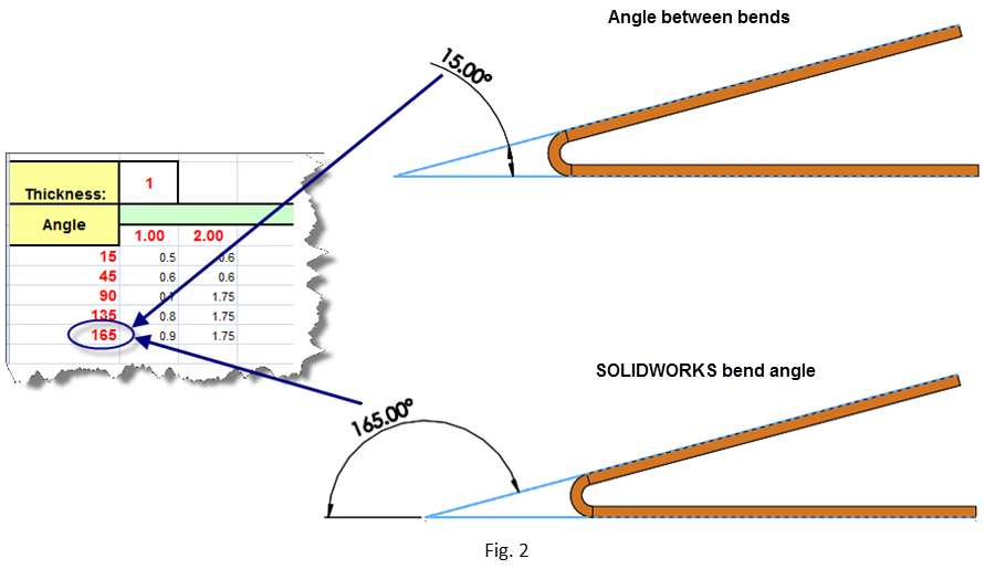
In SOLIDWORKS the bend angle is considered the angle that it takes to bend the flange from its flat position.
The bend table specified angles correlate to the SOLIDWORKS bend angles (Fig. 2)
Flatten Length (Bend Region). Understanding bend allowance.
When a sheet metal body is bent the material around the bend is deformed and stretched. This changes the length of the body. This “stretched” area in the SOLIDWORKS model body is represented by the bend region.
The bend region –by default — is not displayed when the flat pattern is unsuppressed. In order to view this bend region, the user must edit the flat pattern feature and unchecked the “merge bends” option.
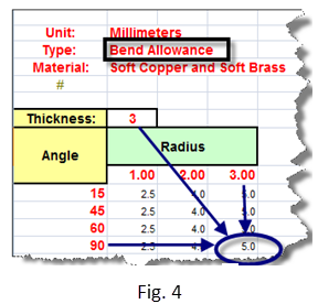
In (Fig. 3), the user has a body with 3 mm in thickness, 3 mm bend radius and a 90 deg bend angle.
Those values in the bend allowance bend table (Fig. 4) show a bend allowance of 5 mm.
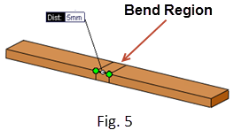
This mean that the body’s bend region length in the flat pattern should be also 5 mm (Fig. 5 )
Understanding Bend deduction
Bend deduction is the other side of the bend allowance equation. We said above that when a sheet metal body was bent the material around the bend was deformed and stretched. To account for that stretch we must deduct that value from the flat body.
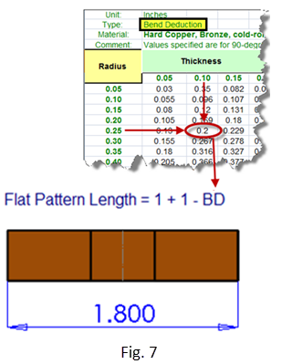
In (Fig. 6), the user has a body with 0.1 inch in thickness, .25 inch bend radius and a 90 deg. bend angle.
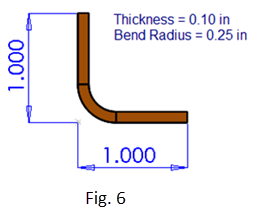
From the bend deduction table (Fig. 7), the bend deduction is 0.2 inch. Therefore, the flatten length will be equal to the sum of the sides –measure from their virtual sharp – minus the indicated bend deduction.
Understanding K-factor
When bending a body, the metal fibers –around the bend region — contract near the bend radius (inner radius) and expand on the opposite side (outer radius). The k-factor is the theoretical neutral axis that experience no deformation.
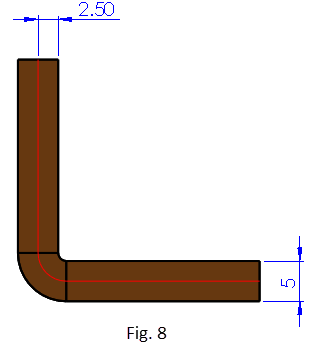
(Fig. 8) shows that a K-factor equal to 0.5 means that this neutral fiber passes at 50% of the material thickness as measured from the bend radius side.
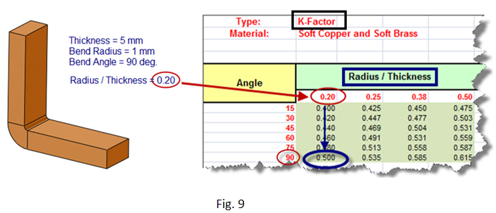
(Fig. 9) shows a sample part. Using our default K-factor bend table, the Radius/Thickness ratio is 0.20.
At a 90 deg. bend angle we have a K-factor equal to 0.5
(Fig 10) shows that the length of the “neutral fiber” — we sketched in the part,– must have the same length as the flatten length.
Next month we will explore the bend gauge/table guidelines rules.
Original post created by Mario Iocco,Sr. Technical Customer Support Engineer, SolidWorks, Americas
SUBMIT YOUR COMMENT